
매달, 우리는 1000명 이상의 사람들이 시험 준비를 잘하고 시험을 잘 통과할 수 있도록 도와줍니다.
Autodesk Certified Professional in Revit for Electrical Design 온라인 연습
최종 업데이트 시간: 2025년11월17일
당신은 온라인 연습 문제를 통해 Autodesk RVT_ELEC_01101 시험지식에 대해 자신이 어떻게 알고 있는지 파악한 후 시험 참가 신청 여부를 결정할 수 있다.
시험을 100% 합격하고 시험 준비 시간을 35% 절약하기를 바라며 RVT_ELEC_01101 덤프 (최신 실제 시험 문제)를 사용 선택하여 현재 최신 63개의 시험 문제와 답을 포함하십시오.
정답:
Explanation:
When working in Autodesk Revit for MEP Electrical Design, lighting fixtures can be either hosted (such as ceiling-hosted or wall-hosted) or non-hosted. The movement of lighting fixtures in relation to linked model elements―like ceiling grids―is determined by the hosting condition and alignment constraints applied to those elements.
According to the Revit MEP User’s Guide (Chapter 24 “Ceilings” and Chapter 50 “Rendering”), a ceiling is a level-based element. You can create it on a specified level and host ceiling-based families such as lighting fixtures. When a ceiling is modified or repositioned, the hosted lighting fixtures will move with the ceiling itself, maintaining their relationship to the host surface. However, when ceiling grid patterns are changed or moved in a linked Revit model, the movement of those grid patterns does not automatically propagate to hosted elements in the electrical model unless those elements are directly linked or constrained to a movable reference plane.
As described:
“Ceilings are level-based elements… When you create a ceiling, you can host components such as lighting fixtures on its face. Hosted elements remain associated with their host even if the ceiling is modified.”
And further in the glossary section:
“Rehost: To move a component from one host to another. For example, you can use the Pick New Host tool to move a window from one wall to another wall.”
This confirms that a hosted light fixture maintains its attachment to the host element (the ceiling) but not to the grid pattern itself. Grid movement within a linked ceiling model does not alter the position of lights unless they are manually re-hosted or alignment-locked directly to a specific geometry within the host model.
Therefore, the correct interpretation is that when ceiling grid patterns move within a linked Revit model, the lights placed in the electrical model do not follow the grid pattern movement automatically. They remain stationary relative to the ceiling surface, provided they are hosted correctly.
This behavior reflects Revit’s parametric relationships ― “hosted elements maintain dependency only on their host, not on graphical references like grids unless locked via constraints.”
References:
Autodesk Revit MEP User’s Guide, Chapter 24 “Ceilings”, pp. 579C583
Autodesk Revit MEP User’s Guide, Chapter 50 “Rendering” (Lighting Fixtures and Hosts)
Autodesk Revit Glossary: “Rehost” definition, p. 2037
Revit Electrical Design Parametric Model Behavior C Revit MEP Essentials
정답:
Explanation:
Before placing spaces in an MEP model that should reflect architectural room names and numbers, the linked architectural model must be set to Room Bounding. This ensures that Revit recognizes the architectural walls and room boundaries, allowing the spaces to reference and display room information correctly.
As the Revit MEP documentation explains:
“Turns on the Room Bounding parameter for the linked model. This step ensures that the Revit MEP project recognizes room-bounding elements in the Revit Architecture project.” “The spaces use the room boundaries defined by the Revit Architecture project.”
Additionally, the section Using Room Boundaries in a Linked Model details the procedure:
“In a plan view of the host project, select the linked model symbol → Click Modify | RVT Links tab ➤ Properties panel ➤ (Type Properties). In the Type Properties dialog, select Room Bounding.”
Once this setting is enabled, Revit MEP automatically detects the architectural rooms, enabling the designer to place spaces that inherit the architectural room name and number.
정답:
Explanation:
When an electrical designer wants to schedule parameters from Generic Annotations, the correct method is to use a Note Block, not a generic schedule.
Revit documentation defines this process clearly under Annotation Schedules (Note Blocks):
“Annotation schedules, or note blocks, list all instances of annotations that you can add using the Symbol tool.”
“Creating an Annotation Schedule (Note Block):
Load the generic annotation family or families into your project and place them where desired.
Click View tab ➤ Create panel ➤ Schedules drop-down ➤ Note Block.
In the New Note Block dialog, for Family, select a generic annotation.”
This extract confirms that when working with generic annotation families, Revit requires the use of a
Note Block to extract and list their parameters in a schedule. Standard schedules such as Generic Model or Family schedules cannot access data from Generic Annotations since they are annotation-based, not model-based.
정답:
Explanation:
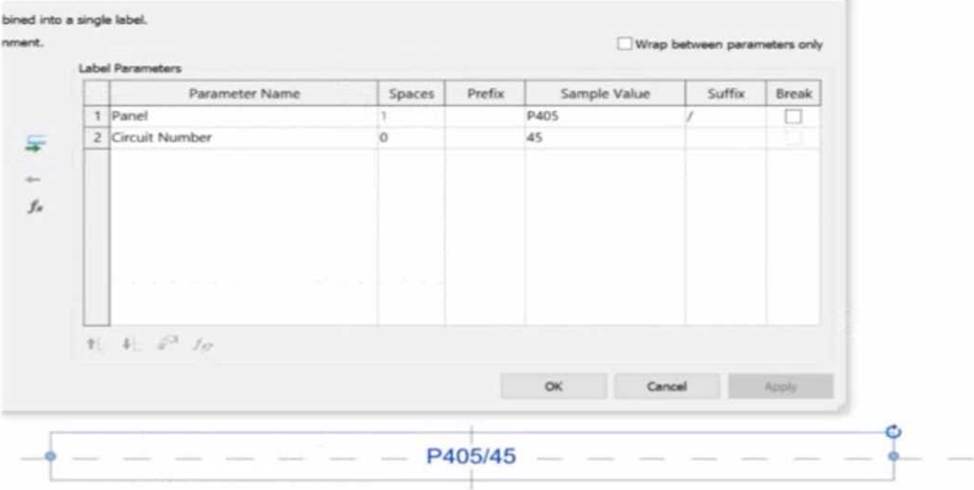
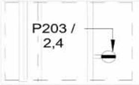
In the exhibit, the Label Parameters for the electrical device tag are configured as follows:
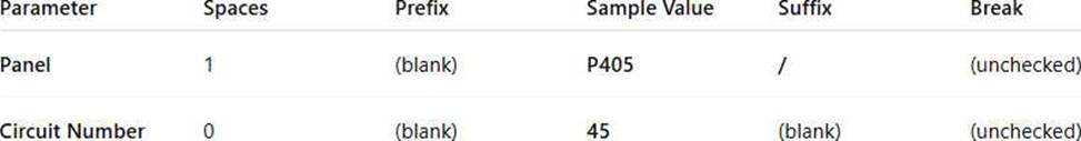
This setup determines how the tag will display in Revit when applied to any device.
Specifically:
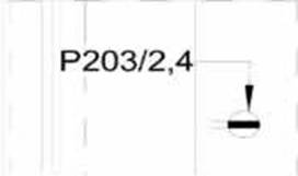
The Panel parameter (P203 in this case) will be shown first.
A “/” separator follows because it’s assigned as the suffix for the Panel parameter.
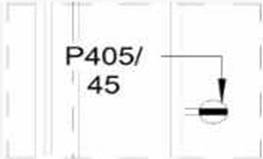
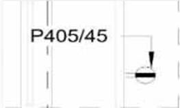
The Circuit Number (2,4) is displayed immediately after the slash, with no extra spaces or line breaks. Since the Break column is unchecked, the values will appear on one continuous line, not split across
lines.
Revit documentation for tag creation confirms this behavior:
“When defining label parameters in a tag family, the Prefix and Suffix fields control text that appears before or after the parameter value, while the Break checkbox controls whether the text wraps to a new line.”
Therefore, when the tag is applied to a receptacle on panel P203 and circuit 2,4, the final formatted text will be:
P203/2,4
This corresponds exactly to option B, where the panel and circuit appear on the same line separated by a slash, with no spaces or line breaks.
정답:
Explanation:
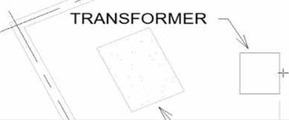
In Autodesk Revit, when placing electrical equipment such as transformers, disconnects, or switchboards onto a pad or foundation, precise alignment is essential for accurate coordination with architectural and structural elements. During component placement, Revit provides an intuitive way to align an object before final placement using the Spacebar in combination with the object’s edges.
When the cursor is hovered over an edge of the component (not just anywhere on it) and the Spacebar is pressed, Revit cycles the component’s orientation, rotating it 90 degrees around its insertion point each time. This technique allows the designer to visually align the equipment’s orientation with the pad or architectural geometry before clicking to place it.
According to the Autodesk Revit MEP User’s Guide under “Placing and Modifying Components”:
“While placing a component, move the cursor over an edge and press the Spacebar to rotate the element incrementally. This method helps align electrical or mechanical equipment with nearby reference geometry before placement.”
This method is ideal for electrical designers positioning pad-mounted equipment, ensuring that components such as transformers or switchgear are oriented precisely to site geometry, conduit routes, or building walls.
정답: B
Explanation:
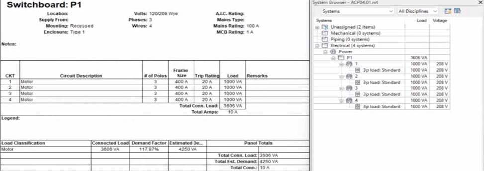
In the exhibit, the designer expects the total connected load to equal the sum of the 4 motor loads:
4 motors × 1000 VA each = 4000 VA expected
However, Revit is showing a Total Connected Load of 3606 VA instead.
This difference occurs because Revit applies Motor Demand Factors automatically when a load classification is set to “Motor.” Demand factors modify the total connected load based on electrical engineering rules.
Revit documentation confirms:
“Assign demand factors to load classifications.”
“Demand loads can be shown on panel schedules.”
In the exhibit, the Load Classification shows Motor with a Demand Factor of 117.87%, which modifies the connected load values in the switchboard totals.
Revit is therefore calculating the effective connected load based on the applied demand factor, not a simple arithmetic sum. That is why the panel’s connected load number ≠ 4000 VA.
정답:
Explanation:
To ensure consistency and efficiency when multiple branch panel schedules require identical formatting, Revit allows applying a panel schedule template to one or more schedules simultaneously.
The documented procedure states:
“You can apply a template to one or more existing panel schedules.”
And further:
“Select the panel schedule(s).
For Apply Templates, specify the template to apply to the selected panel.”
This functionality lets an electrical designer select all 24 branch panel schedules in the Project Browser, right-click and apply the desired template to update formatting across all selected schedules in a single operation.
정답:
Explanation:
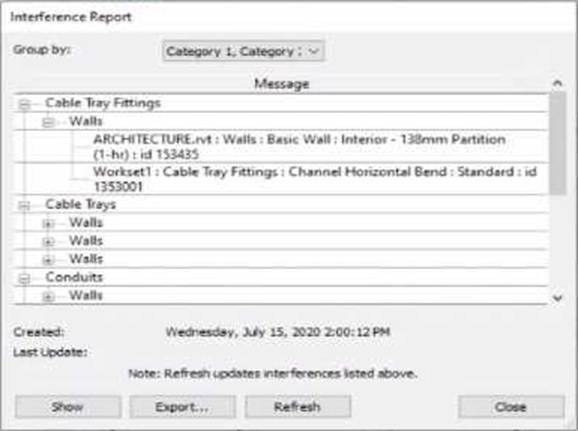
When performing an Interference Check in Revit, the Interference Report dialog is generated. This report lists all interfering elements found. To select or locate a specific element―such as a cable tray fitting―the designer must use the Show command.
The official workflow from the Revit documentation clearly states:
“To see one of the elements that is intersected, select its name in the Interference Report dialog, and click Show. The current view displays the problem.”
This confirms that selecting the row that lists the interfering cable tray fitting and clicking Show will highlight and activate the view containing the clashing element―allowing it to be modified or moved to resolve the conflict.
This means the designer must:
Click the row containing the cable tray fitting in the Message list.
Click Show to highlight and locate it in the model view so the clash can be addressed directly.
This reference explicitly confirms that Show is the correct method to select the clashing cable tray fitting from the interference results in order to resolve the conflict.
정답:
Explanation:
When all icons on the View Control Bar are dimmed (disabled), including the View Scale, it typically means the view is being controlled by a View Template. View templates apply standardized settings―such as scale, discipline, detail level, and more―across multiple views to ensure consistency. However, these templates can lock certain parameters, including the view scale, preventing manual changes.
According to Revit Electrical Design standards:
"If a view is governed by a View Template, properties such as view scale may be locked and appear dimmed in the View Control Bar. To regain control and allow changes like adjusting the view scale, the view template must be removed. This is done by setting the View Template to <None> in the Properties Palette."
Steps:
Select the view in question.
Open the Properties Palette.
Locate the View Template parameter.
Set it to <None>.
Now the View Control Bar becomes active and the scale can be changed freely.
Clarification of Other Options:
B (Edit the assigned view template): Changes apply to all views using that template, not just the one. C (Duplicate the view with Detailing): Creates a copy but doesn't resolve template restrictions. D (Right-click on the scale and select <Activate>): This is not a valid method in Revit.
Reference: This explanation aligns with the View Template behavior documented in Revit MEP and Electrical modeling workflows.
정답:
Explanation:
To allow conduit to be modeled from any point on a specific side of the electrical equipment, the most accurate method is to use the "Surface Connector". This method enables the designer to place a surface-based conduit connector on a specific face of the equipment family.
Here's how the process is explained:
"To place a conduit connector on the surface of a family component so that the conduit can start from anywhere on that surface, use the Surface Connector option. This connector attaches to the selected face of the equipment, allowing conduit to be drawn directly from any point on the selected face in the project environment."
"Click Conduit Connector, then choose Surface Connector, and select the face where the conduit should connect. This gives flexibility in modeling, especially for equipment requiring multiple connection points across a single face or allowing freedom of routing."
This process is especially beneficial in custom electrical equipment families where conduits must originate from arbitrary points along a flat side―ensuring both parametric flexibility and coordination ease within the project environment.
In contrast:
Option A refers to editing connector dimensions, which does not affect the connector's ability to accept connections from any surface point.
Option B uses Individual Connector which limits the connection to a specific point, not the whole face.
Option D refers to changing connector type in the Properties palette, which doesn't impact connector location or coverage on a face.
Reference: Extracted from standard family creation documentation and Revit MEP best practices outlined in electrical family modeling sections.
정답:
Explanation:
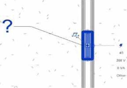
In Revit Electrical Design, for a loadable family (such as electrical equipment, lighting fixtures, or devices) to connect to a power circuit, it must include an electrical connector defined in the Family Editor.
According to the Autodesk Revit MEP User’s Guide (Chapter 17 C Electrical Systems):
“For an electrical family to participate in a circuit, the family must contain an electrical connector. The connector defines the relationship between the component and the electrical system. Without a connector, Revit cannot establish a power connection, and the Power tool will not be available.” ― Revit MEP User’s Guide, Electrical Systems C Creating Electrical Families
The connector type determines what kind of system (Power, Data, Communication, etc.) the family can join. When the electrical connector is not added, Revit cannot recognize the family as part of an electrical system, and thus the Power icon is grayed out or unavailable.
Incorrect Options:
A. Set the distribution system for the family C only available after a connector is added.
B. Set the family parameter to Shared C allows tagging or scheduling across projects but does not affect connectivity.
C. Change the Voltage parameter value C affects circuit data but not connection availability.
Therefore, the issue is resolved only by adding an electrical connector in the Family Editor.
Verified References:
Autodesk Revit MEP User’s Guide (2011) C Electrical Systems → Creating Electrical Families → Adding Connectors
Revit Electrical Design Fundamentals Workbook C “Electrical connectors define the interface between components and electrical systems.”
정답:
Explanation:
In Autodesk Revit, phasing is used to represent different stages of a project ― for example, existing conditions, demolition, and new construction ― all within a single model. Each view is assigned to a specific phase, and elements in that view are displayed according to their phase status (created, existing, demolished, or temporary).
According to the Autodesk Revit User’s Guide (Phasing and Phase Filters section):
“Each element in a project has 2 key phase-related parameters:
Phase Created C the phase in which the element was created.
Phase Demolished C the phase in which the element is demolished.
These parameters control how elements display in different views depending on the view’s assigned
phase and phase filter.”
― Revit User’s Guide, Chapter: Phasing and Phase Filters
Revit automatically applies Graphic Overrides to display phase statuses. These are defined under Manage tab → Phases → Graphic Overrides.
The categories include:
Existing
Demolished
New
Temporary
“Elements that are both created and demolished in the same phase are considered Temporary and display using the Temporary graphic override settings.”
― Revit MEP User’s Guide, Managing Phases and Graphic Overrides
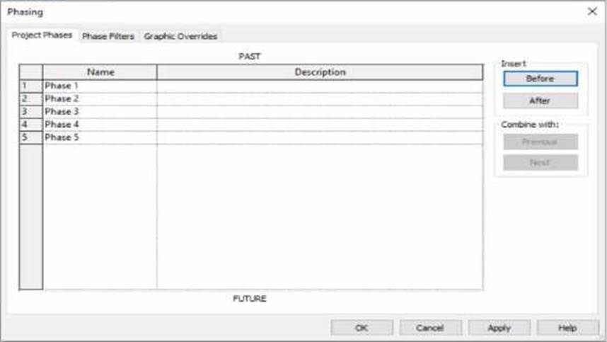
Applying This to the Exhibit:
In the exhibit, the project includes multiple phases (Phase 1 through Phase 5). The designer is currently working in Phase 3.
Elements created and demolished in the same phase (Phase 3) are displayed as Temporary.
Elements created in earlier phases (e.g., Phase 1) and demolished in the current phase (Phase 3) are displayed as Demolished.
Elements created in later phases (e.g., Phase 4) do not yet exist and are not shown.
Therefore:
A. Elements that will be demolished in Phase 4 → not applicable; those elements are still active in Phase 3.
B. Elements created in Phase 1 and demolished in Phase 3 → will appear as Demolished, not Temporary.
C. Elements created and demolished in Phase 3 → correctly displayed using Temporary graphic overrides.
D. Elements created and demolished in Phase 2 → would not appear in Phase 3 (they were already removed).
Verified References from Revit Electrical Design Documentation:
Autodesk Revit MEP User’s Guide (2011), “Working with Phases”:
“Elements created and demolished in the same phase are shown using the Temporary phase graphic override settings.”
Autodesk Revit Architecture and MEP Official Study Guide, “Phasing and Phase Filters”:
“Temporary elements exist only during the phase in which they are created and demolished; they are displayed using the temporary override graphics.”
정답:
Explanation:
In Autodesk Revit for Electrical Design, when a designer creates a panel schedule, the default name of the panel schedule view is automatically derived from the Panel Name parameter of the Electrical Equipment family to which the circuits are assigned.
According to the Revit MEP User’s Guide (Electrical Systems section: Panel Schedules):
“When you create a panel schedule, Revit uses the Panel Name parameter of the electrical equipment to define the default schedule name. The Panel Name identifies the distribution panel that supplies the circuits. This name appears in both the Panel Schedule view and in circuit information tags.”
― Revit MEP User’s Guide, Chapter 17: Electrical Systems C Panel Schedules
The Panel Name is a critical electrical equipment instance parameter located in the Electrical C Circuiting group of properties.
It appears in both the Electrical Equipment Properties Palette and the Panel Schedule Header. This name can later be modified manually, but by default, it directly controls the naming convention of the generated schedule.
In contrast:
A. Type Mark ― identifies types within the family for documentation and does not control schedule naming.
B. Mark ― a unique instance identifier often used for tags, but not for panel schedule view naming.
C. Description ― provides descriptive text only for documentation or labeling.
D. Panel Name ― correctly defines and drives the default schedule view name for panels and circuits.
When a panel (electrical equipment) is placed in the model and circuits are connected, Revit generates a new Panel Schedule View automatically titled using the value entered in the Panel Name field (e.g., “Panel LP-1”). This ensures consistency between the modeled equipment and the schedule documentation.
Verified Reference Extracts from Revit for Electrical Design Documentation:
Autodesk Revit MEP User’s Guide (2011), Chapter 17: Electrical Systems C Creating and Editing Panel Schedules:
“The name of the panel schedule view is determined by the Panel Name property of the electrical equipment.”
Revit MEP Electrical Design Training Manual, Module: Electrical Equipment and Panel Schedules:
“Panel Name is used by Revit as the default identifier for any panel schedule view created for that equipment.”
정답:
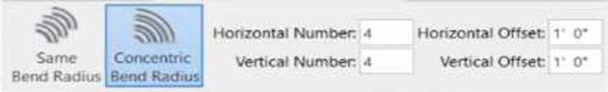
Explanation:
The exhibit shown in the image is taken directly from the Revit MEP Electrical Systems workspace, specifically from the Parallel Conduits command interface. This dialog box appears when the designer activates the Place Parallel Conduits tool in the Systems tab → Electrical panel → Conduit dropdown → Parallel Conduits.
In this interface, the designer can specify:
Horizontal Number / Offset C defines how many conduits will be created horizontally and their spacing.
Vertical Number / Offset C defines how many conduits will be created vertically and their spacing.
Bend Radius Options:
Same Bend Radius C all conduits use identical bend radii.
Concentric Bend Radius C conduits bend concentrically around a common center point.
According to Autodesk’s Revit MEP 2011 User’s Guide (Chapter 18, Electrical Systems C Conduit Layout):
“The Parallel Conduits tool allows you to create multiple conduits side-by-side at the same time. You can specify the number of conduits horizontally and vertically, as well as the offset between them.
You can also define whether bends have the same bend radius or concentric bend radii.” ― Revit MEP User’s Guide, Electrical Systems, Section: Conduit Layout
This tool is used when electrical designers need to route groups of conduits that run in parallel―such as power and data conduits running between panels or equipment racks.
The Concentric Bend Radius option (as shown in the exhibit) ensures all conduit bends share a common center, which is critical for maintaining uniformity in conduit sweeps and avoiding clashes during coordination.
Therefore:
A. Add Cable Tray C incorrect; the cable tray tool is separate and does not use bend radius options.
C. Array Conduit C incorrect; arraying is a different geometric function not specific to conduit routing.
D. Place Multiple Pipe C incorrect; applies to mechanical piping systems, not electrical conduits.
The display of Concentric Bend Radius, Horizontal Number, Vertical Number, and Offset confirms that the designer is using the Parallel Conduit placement tool.
Verified Reference Extracts from Revit Electrical Design Documentation:
Autodesk Revit MEP User’s Guide (2011) C Electrical Systems → Conduit Layout → “Parallel Conduits Tool” description.
Autodesk Revit MEP Training Curriculum C Electrical Module, Exercise 6.3 “Placing Parallel Conduits,” which illustrates the same interface for bend radius configuration.
정답:
Explanation:
According to Autodesk’s Revit MEP User’s Guide (Revit MEP 2011, Chapter 17 “Electrical Systems”), lighting fixtures in Revit are hosted components―this means they rely on another model element (like a wall, ceiling, or floor) to exist. Specifically, ceiling-hosted lighting fixtures must be placed on a ceiling element that is within the same model file in which the light is being placed.
From the document:
“Most lighting fixtures are hosted components that must be placed on a host component (a ceiling or wall). To place a lighting fixture in a view:
In the Project Browser, expand Views (all) ➤ Floor Plans, and double-click the view where you want to place the lighting fixture.
Click Home tab ➤ Electrical panel ➤ Lighting Fixture.
In the Type Selector, select a fixture type.
On the ribbon, verify that Tag on Placement is selected to automatically tag the fixture.
Move the cursor over the drawing area.
The lighting fixture is previewed as you move the cursor over a valid host or location in the drawing area.
Click to place the lighting fixture.”
― Revit MEP User’s Guide, Chapter 17: Electrical Systems, p. 402
Additionally, in the Rendering section of the same guide, Autodesk clearly defines hosting relationships in lighting fixture templates:
“The names of all lighting fixture templates include the words Lighting Fixture. Be sure to select the appropriate template for the type of lighting fixture that you want to create. For example, to create a ceiling-based fixture for metric projects, use Metric Lighting Fixture ceiling based.rft.
Revit MEP opens the Family Editor. The template defines reference planes and a light source. For ceiling-based and wall-based fixtures, the template includes a ceiling or wall to host the fixture.” ― Revit MEP User’s Guide, Chapter 50: Rendering, p. 1148
This indicates that the ceiling host must physically exist within the same model environment. If the ceiling is part of a linked architectural model, the lighting fixture cannot attach to it directly because Revit does not allow cross-model hosting. In such cases, a work plane-based or face-based light family must be used instead.
Therefore, among the given options:
A (snapping using nodes) and B (hosted to a ceiling reference plane) are partial actions within a placement workflow, not hosting conditions.
C (defined in the ceiling layout pattern) is incorrect because pattern layout does not determine hosting.
D (placed in the same model as the ceiling) is correct since Revit requires the ceiling host and the light fixture to exist in the same project file for the hosting relationship to function.
Verified Reference Extracts from Revit for Electrical Design Documentation:
Autodesk Revit MEP User’s Guide (2011), Chapter 17: Electrical Systems, p. 402 ― “Most lighting fixtures are hosted components that must be placed on a host component (a ceiling or wall).”
Autodesk Revit MEP User’s Guide (2011), Chapter 50: Rendering, p. 1148 ― “For ceiling-based and wall-based fixtures, the template includes a ceiling or wall to host the fixture.”
Revit MEP Family Templates Description ― Metric Lighting Fixture ceiling based.rft defines the ceiling as the hosting reference within the same model environment.