
매달, 우리는 1000명 이상의 사람들이 시험 준비를 잘하고 시험을 잘 통과할 수 있도록 도와줍니다.
Data Center, Associate (JNCIA-DC) 온라인 연습
최종 업데이트 시간: 2025년10월09일
당신은 온라인 연습 문제를 통해 Juniper JN0-281 시험지식에 대해 자신이 어떻게 알고 있는지 파악한 후 시험 참가 신청 여부를 결정할 수 있다.
시험을 100% 합격하고 시험 준비 시간을 35% 절약하기를 바라며 JN0-281 덤프 (최신 실제 시험 문제)를 사용 선택하여 현재 최신 65개의 시험 문제와 답을 포함하십시오.
정답:
Explanation:
Bidirectional Forwarding Detection (BFD) is a network protocol used to detect failures in the network path between two devices quickly.
Step-by-Step Breakdown:
Path Failure Detection:
BFD provides a low-overhead mechanism for detecting failures in forwarding paths across Layer 3 networks. It is much faster than traditional routing protocol timers and can detect failures within milliseconds.
BFD in Routing:
BFD can be integrated with routing protocols like OSPF, BGP, or IS-IS to trigger a faster convergence when a network path goes down.
Juniper
Reference: BFD Configuration: Juniper devices use BFD to monitor network paths and ensure fast failure detection, enhancing network resilience.
정답:
Explanation:
An IP fabric is a network architecture commonly used in data centers to provide scalable, high-throughput connectivity using a spine-leaf topology.
Step-by-Step Breakdown:
Layer 3 Routing Protocol:
An IP fabric relies on a Layer 3 routing protocol, typically BGP or OSPF, to provide routing between the leaf and spine switches. This ensures efficient traffic forwarding across the network. Single Connection Between Spine and Leaf:
In an IP fabric, each leaf switch connects to every spine switch with a single connection. This ensures that traffic between any two leaf switches can travel through the spine layer in just two hops.
Juniper
Reference: Spine-Leaf Design: Juniper’s IP fabric implementations are designed for scalability and low-latency
routing, often using protocols like BGP for Layer 3 control.
정답:
Explanation:
When configuring an aggregate route, you have options for how to handle traffic that matches the route but does not match any more specific route in the routing table.
Two actions can be taken:
discard and reject.
Step-by-Step Breakdown:
Discard:
The discard option will silently drop packets that match the aggregate route. No notification is sent to the sender, and the packet is simply dropped.
Reject:
The reject option will drop the packet and also send an ICMP Destination Unreachable message back to the sender. This informs the sender that the packet could not be delivered because there is no specific route available.
Juniper
Reference: Aggregate Routes: The reject and discard next-hop options provide different levels of feedback when packets cannot be routed, and they can be used to control how unreachable destinations are handled.
정답:
Explanation:
The source MAC address in the Ethernet header is used to populate the bridging table (also called the MAC address table) on a switch. When a frame arrives at a switch, the switch examines the source MAC address and records it along with the ingress port in its MAC address table.
Step-by-Step Breakdown:
Learning Process:
When an Ethernet frame arrives on a switch port, the switch looks at the source MAC address and adds this MAC address to the MAC table along with the port it was received on. This process is called MAC learning.
Purpose:
The switch uses this information to determine the correct port to send frames destined for that MAC address in future transmissions, thus ensuring efficient Layer 2 forwarding. Juniper
Reference: Ethernet Switching: Juniper switches use source MAC addresses to build and maintain the MAC address table, which is essential for Layer 2 switching.
정답:
Explanation:
When a MAC limiting violation occurs on a Juniper switch, the switch will perform the following actions by default:
Step-by-Step Breakdown:
Port Disabled:
When the number of MAC addresses on an interface exceeds the configured limit, the port is automatically disabled to prevent further violations. This is a protective mechanism to prevent MAC address flooding.
Packet Dropped:
Additionally, packets from the violating MAC address are dropped to prevent any further communication from that address. This ensures that only valid MAC addresses are allowed to communicate through the interface.
Example Configuration:
set ethernet-switching-options secure-access-port interface <interface-name> mac-limit 5
If more than five MAC addresses are learned, the port is disabled, and excess packets are dropped.
Juniper
Reference: MAC Limiting: When the switch detects a MAC limiting violation, it disables the port and drops further packets from the violating MAC addresses to maintain network security.
정답:
Explanation:
To verify that your router is learning routes from a remote BGP peer at a specific IP address (e.g., 10.10.100.1), the correct command to use is show route receive-protocol bgp.
Step-by-Step Breakdown:
BGP Route Learning:
The show route receive-protocol bgp command displays the routes that have been received from a specified BGP peer. This helps in confirming that the remote peer is sending routes correctly and that your router is receiving them.
Command Example:
show route receive-protocol bgp 10.10.100.1
This will show all routes that have been received from the BGP peer with IP address 10.10.100.1.
Juniper
Reference: BGP Route Verification: Use this command to troubleshoot and verify that routes from a specific BGP peer are being received.
정답:
Explanation:
To display the mapping between VLAN IDs and ports on a Juniper switch, the show vlans command is used.
Step-by-Step Breakdown:
VLAN Information:
The show vlans command displays detailed information about VLAN configurations, including the VLAN ID, associated interfaces (ports), and VLAN membership.
Command Example:
show vlans
This command will provide an output listing each VLAN, its ID, and the interfaces associated with the VLAN, enabling network engineers to quickly verify VLAN to port mappings.
Juniper
Reference: VLAN Verification: Use the show vlans command to verify which VLANs are configured on the switch and the ports that are members of those VLANs.
정답:
Explanation:
EVPN (Ethernet Virtual Private Network) is a standard protocol used for building Layer 2 and Layer 3
VPNs over an IP or MPLS network. The signaling protocol used for EVPN is BGP (Border Gateway Protocol).
Step-by-Step Breakdown:
BGP as the EVPN Signaling Protocol:
EVPN uses BGP to exchange MAC address reachability information between routers (PE devices). This enables devices to learn which MAC addresses are reachable through which PE devices, facilitating Layer 2 forwarding across an IP or MPLS core.
BGP Extensions for EVPN:
BGP is extended with new address families (e.g., EVPN NLRI) to carry both MAC and IP address information, allowing for scalable and efficient multi-tenant network solutions. Juniper
Reference: Junos EVPN Configuration: Juniper uses BGP as the control plane for EVPN to exchange MAC and IP route information between different data center devices.
정답:
Explanation:
Filter-Based Forwarding (FBF) in Junos OS allows traffic to be routed based on specific criteria such as source address, rather than just the destination address. This is useful in scenarios like policy routing or providing multiple paths for different types of traffic.
Step-by-Step Breakdown:
Instance-Type Forwarding:
You must create an instance-type forwarding routing instance. This routing instance allows for different routing tables based on the incoming packet filter.
Command:
set routing-instances FBF-instance instance-type forwarding
Match Filter:
You need to create a filter to match the traffic that will be forwarded according to your custom routing policy. This filter is applied to an interface to determine which traffic will use the custom forwarding instance.
Command Example:
set firewall family inet filter FBF-filter term 1 from source-address <address> set firewall family inet filter FBF-filter term 1 then routing-instance FBF-instance RIB Group:
A RIB (Routing Information Base) group is necessary to share routes between the primary routing table and the custom routing instance. This allows FBF traffic to use the routing information from other routing tables.
Command Example:
set routing-options rib-groups FBF-group import-rib inet.0
set routing-instances FBF-instance routing-options rib-group FBF-group
Juniper
Reference: FBF Configuration: Filter-based forwarding requires these specific steps to redirect traffic to a custom routing table based on filter criteria.
정답:
Explanation:
When creating a LAG (Link Aggregation Group) in Junos, the duplex settings and link speed must be the same across all member interfaces.
Step-by-Step Breakdown:
LAG Overview:
A LAG combines multiple physical interfaces into a single logical interface to increase bandwidth and provide redundancy. All member links must act as a single cohesive unit.
Interface Requirements:
Duplex: All member interfaces must operate in the same duplex mode (either full-duplex or half-duplex). Mismatched duplex settings can cause performance issues, packet drops, or interface errors. Link Speed: All interfaces in the LAG must have the same link speed (e.g., all interfaces must be 1 Gbps or 10 Gbps). Mismatched speeds would prevent the interfaces from functioning correctly within the LAG.
Configuration and Validation: Ensure that all member interfaces have identical settings before adding them to the LAG. These settings can be checked using the show interfaces command, and the LAG can be configured using:
set interfaces ae0 aggregated-ether-options link-speed 10g set interfaces ge-0/0/1 ether-options 802.3ad ae0 Juniper
Reference: LAG Configuration: Duplex and link speed must be consistent across member interfaces to ensure proper LAG operation in Juniper devices.
정답:
Explanation:
When advertising OSPF routes into BGP, the appropriate routing policy should be applied as an export policy in BGP.
Step-by-Step Breakdown:
OSPF to BGP Route Advertisement:
Routes learned via OSPF (a dynamic IGP) need to be exported into BGP to be advertised to external BGP peers. In Junos OS, this is done using export policies.
Export Policies in BGP:
An export policy controls which routes are advertised out of a BGP session. In this scenario, the routing policy must be applied to BGP as an export policy to export the OSPF-learned routes to external BGP peers.
Policy Configuration:
Example configuration:
set policy-options policy-statement EXPORT_OSPF term 1 from protocol ospf set policy-options policy-statement EXPORT_OSPF term 1 then accept
set protocols bgp group <group-name> export EXPORT_OSPF This policy ensures that only OSPF routes are exported into BGP. Juniper
Reference: Routing Policy: Export policies are used in BGP to control route advertisements to peers, including those learned via OSPF.
정답:
Explanation:
In a three-stage IP fabric (also known as a Clos fabric), traffic between any two points (ingress to egress) in the fabric is only two hops away.
Step-by-Step Breakdown:
Three-Stage IP Fabric:
Leaf Layer: Leaf switches connect directly to servers and edge devices.
Spine Layer: Spine switches provide connectivity between leaf switches but do not connect to each
other directly.
Two-Hop Communication:
In this architecture, every leaf switch is connected to every spine switch. Therefore, when a packet enters the fabric via an ingress leaf switch, it is forwarded to a spine switch, which then directs the packet to the correct egress leaf switch. This path always involves exactly two hops: Ingress leaf → Spine → Egress leaf.
Benefits:
This consistent two-hop path ensures predictable latency and makes the network highly scalable
while maintaining low complexity.
Juniper
Reference: IP Fabric Architecture: This two-hop property of Clos fabrics is a hallmark of spine-leaf designs, as supported by Juniper's QFX and EX switches in data centers.
정답:
Explanation:
The BGP AS (Autonomous System) path attribute is crucial in path selection and loop prevention.
Each BGP router appends its local AS number to the beginning of the AS path when it advertises a route to an external BGP (eBGP) peer.
Step-by-Step Breakdown:
AS Path Attribute:
The AS path is a sequence of AS numbers that a route has traversed to reach a destination. Each AS adds its number to the front of the path, allowing BGP to track the route’s history.
Why the Local AS is Added at the Beginning:
When advertising a route to an eBGP neighbor, a BGP router adds its own AS number to the beginning of the AS path. This ensures that the AS path reflects the route's journey accurately from the origin to the destination, and prevents loops in BGP. If the route returns to the same AS, the router will detect its AS number in the path and reject the route, preventing routing loops.
Order of the AS Path:
The order is significant because BGP uses it to select the best path. A shorter AS path is preferred, as it indicates fewer hops between the source and destination. Juniper
Reference: AS Path Attribute: Junos devices append the local AS at the start of the AS path before advertising the route to an external peer.
정답:
Explanation:
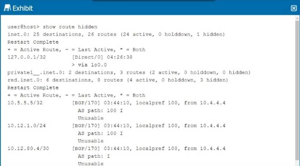
In the exhibit, the BGP routes are marked as hidden. This typically happens when the routes are not considered valid for use, but they remain in the routing table for reference. One common reason for BGP routes being hidden is that the next hop for these routes is unreachable.
Step-by-Step Breakdown:
BGP Next Hop:
In BGP, when a route is received from a neighbor, the next hop is the IP address that must be reachable for the route to be used. If the next hop is unreachable (i.e., the router cannot find a path to the next-hop IP), the route is marked as hidden.
Analyzing the Exhibit:
The exhibit shows that the BGP next hop for all hidden routes is 10.4.4.4. If this IP is unreachable, the BGP routes from that neighbor will not be considered valid, even though they appear in the routing table.
Verification:
Use the command show route 10.4.4.4 to check if the next-hop IP is reachable.
If the next-hop is not reachable, the BGP routes will be hidden. Resolving the next-hop reachability issue (e.g., fixing an IGP route or an interface) will allow the BGP routes to become active. Juniper
Reference: Junos Command: show route hidden displays routes that are not considered for forwarding. Troubleshooting: Check the next hop reachability for hidden BGP routes using show route <next-hop>.
정답:
Explanation:
An IP fabric is a network topology designed to provide a scalable, low-latency architecture that is
typically implemented in modern data centers. It uses spine and leaf switches and enables efficient
traffic load sharing across the network.
Step-by-Step Breakdown:
Spine-Leaf Architecture:
Leaf Devices: These switches connect to servers and edge devices within the data center. Each leaf switch connects to every spine switch.
Spine Devices: These high-performance switches interconnect all the leaf switches. There are no direct connections between leaf switches or spine switches. This architecture ensures that any two endpoints within the fabric are only one hop away from each other, minimizing latency.
Traffic Load Sharing:
An IP fabric leverages Equal-Cost Multipath (ECMP) to distribute traffic evenly across all available paths between leaf and spine switches, providing effective load balancing. This ensures that no single link becomes a bottleneck and that traffic is distributed efficiently across the network. Juniper
Reference: Juniper provides QFX Series switches optimized for IP fabric topologies, allowing for scalable deployments in modern data centers.
EVPN-VXLAN: Often used in IP fabrics to extend Layer 2 services across the fabric with Layer 3 underlay, enabling both efficient routing and bridging.