
매달, 우리는 1000명 이상의 사람들이 시험 준비를 잘하고 시험을 잘 통과할 수 있도록 도와줍니다.
Autodesk Certified Professional in AutoCAD for Design and Drafting 온라인 연습
최종 업데이트 시간: 2025년11월17일
당신은 온라인 연습 문제를 통해 Autodesk ACP-01101 시험지식에 대해 자신이 어떻게 알고 있는지 파악한 후 시험 참가 신청 여부를 결정할 수 있다.
시험을 100% 합격하고 시험 준비 시간을 35% 절약하기를 바라며 ACP-01101 덤프 (최신 실제 시험 문제)를 사용 선택하여 현재 최신 47개의 시험 문제와 답을 포함하십시오.
정답:
Explanation:
According to the search results123, a rectangular array command creates copies of objects in a regularly spaced rectangular pattern. You can adjust the spacing and number of rows and columns by dragging the grips on the array preview or modifying values on the Array context ribbon.
https://knowledge.autodesk.com/support/autocad/learn-explore/caas/CloudHelp/cloudhelp/2020/ENU/AutoCAD-Core/files/GUID-181BF535-D6F4-4B90-B04D-EB99C5488DAB-htm.html
정답:
Explanation:
an annotative hatch is a hatch that automatically adjusts its scale and size to match the viewport scale. This means that the hatch pattern will look the same regardless of how you zoom in or out of the viewport.
To create an annotative hatch, you need to:
✑ Set the annotation scale tool to 1:1
✑ Create your hatch as usual
✑ In the properties palette, make the hatch annotative
✑ Add annotation scales to the hatch as needed
This will create a hatch that displays correctly at different viewport scales.
https://forums.autodesk.com/t5/autocad-forum/annotative-hatch/td-p/2651268
정답:
Explanation:
According to the AutoCAD for Design and Drafting documents1, the command that should be typed at the command line in order to start creating a line for drawing reference that starts at a defined point and extends to infinity in the designated direction is XLINE2. This command creates a construction line, which is a type of reference line that can help you manage accurate parameters of your drawing2. You can also use point objects as nodes or reference geometry for object snaps and relative offsets3.
정답:
Explanation:
The column you should use in the Layer Properties Manager to prevent a layer from being displayed in the active viewport only is "VP Freeze". The VP Freeze column allows you to control the visibility of layers in specific viewports. When you freeze a layer in the VP Freeze column, it is only hidden in the active viewport and remains visible in other viewports. On the other hand, when you freeze a layer with the Freeze column, it becomes hidden in all viewports. Therefore, VP Freeze is the column you should use to hide a layer in a specific viewport only.
https://help.autodesk.com/cloudhelp/2015/ENU/AutoCAD-LT/files/GUID-B297EBD9-D68C-47E1-87CE-1B3798496599.htm
정답:
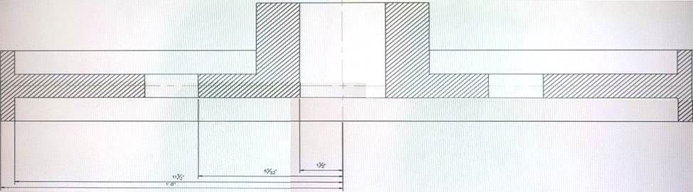
Explanation:
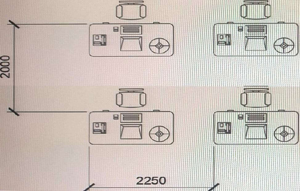
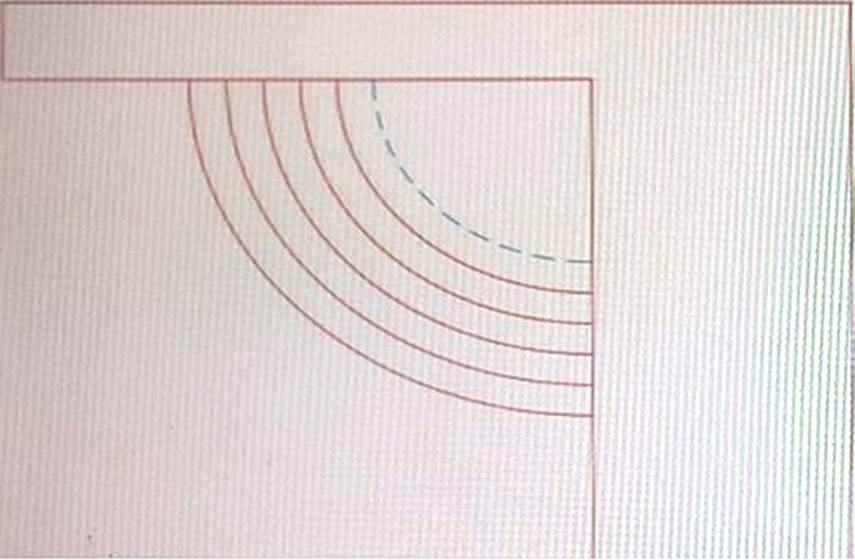
The Current prompt should be used to make sure that the edge of the top step is shown in a different linetype, as shown by the dashed line in the exhibit. This way, you can set a different linetype for your current layer before using the OFFSET command4. https://knowledge.autodesk.com/support/autocad/learn-explore/caas/CloudHelp/cloudhelp/2021/ENU/AutoCAD-Core/files/GUID-C0E4246D-C420-42BD-A6FC-8B1852EFD005-htm.html
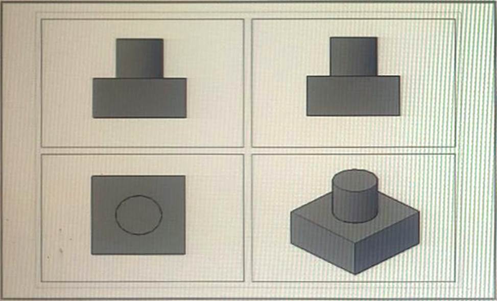
정답: 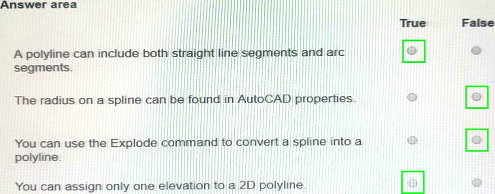
Explanation:
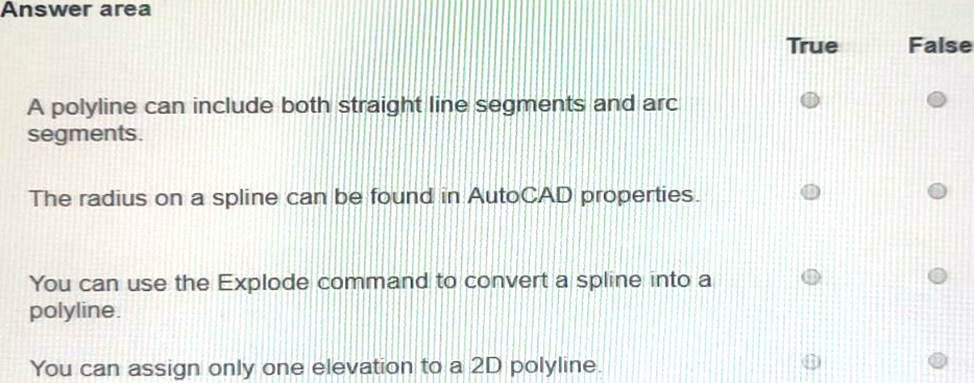
True
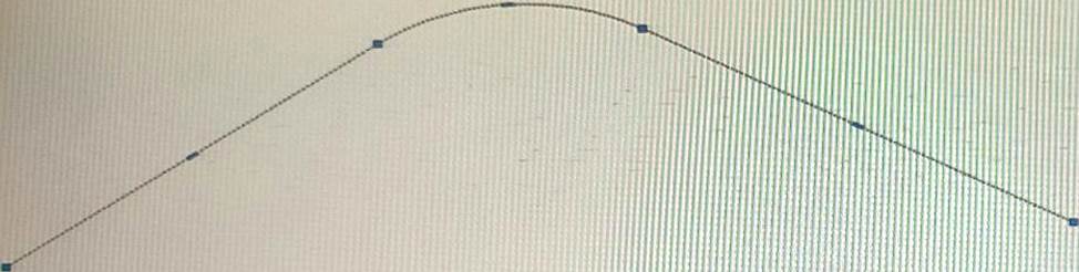
정답: 
Explanation:
✑ FalseYou cannot convert an arc to a line by hovering over the center grip of the arc segment. You need to convert the arc to a polyline first, then use the FLATTEN command, and answer YES to remove hidden lines. Then you can explode the polyline to get line segments. https://forums.autodesk.com/t5/autocad-forum/autocad-is-it-possible-to-convert-an-arc-to-a-segemented-line/td-p/2933624
✑ Falseyou can edit the polyline width by hovering over certain grips if they are vertex grips or midpoint grips. However, if they are arc segment grips, you cannot edit the width by hovering over them1. Therefore, the statement is false. https://knowledge.autodesk.com/support/autocad/learn-explore/caas/CloudHelp/cloudhelp/2015/ENU/AutoCAD-Core/files/GUID-2070C02C-E18A-4333-BDC4-240F49F1C102-htm.html
✑ Falseyou can add a new vertex by hovering over certain grips if they are edge grips or midpoint grips. However, if they are vertex grips or arc segment grips, you cannot add a new vertex by hovering over them2. Therefore, the statement is false.
정답:
Explanation:
a layout viewport is a window that displays a view of model space on a layout tab. You can create multiple layout viewports to display different views of your model at different scales.
To create the viewports in a layout tab, you can use three methods:
✑ From the Viewports dialog box: select a viewport configuration
✑ Create individual viewports by using the MVIEW command
✑ From the View Manager dialog box, generate named views and add them as layout viewpoints
These methods will allow you to create and arrange viewports on your layout tab. https://knowledge.autodesk.com/support/autocad/learn-explore/caas/CloudHelp/cloudhelp/2018/ENU/AutoCAD-Core/files/GUID-2B5D404A-DCAB-4AF6-A5C1-51593B38F519-htm.html
정답:
Explanation:
array items are contained in a single array object, similar to a block. You can change the number of these items and their spacing in an associative array.
Based on 2, you can move an item in an associative array by pressing and holding the Ctrl key, and then selecting the items you want to move.
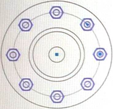
since explode is the command that separates objects into individual objects. Disassociate, ungroup and break are not valid commands for associative arrays. https://knowledge.autodesk.com/support/autocad/learn-explore/caas/CloudHelp/cloudhelp/2020/ENU/AutoCAD-Core/files/GUID-27321B8F-C67E-4EF9-9A25-C5444330E5F2-htm.html
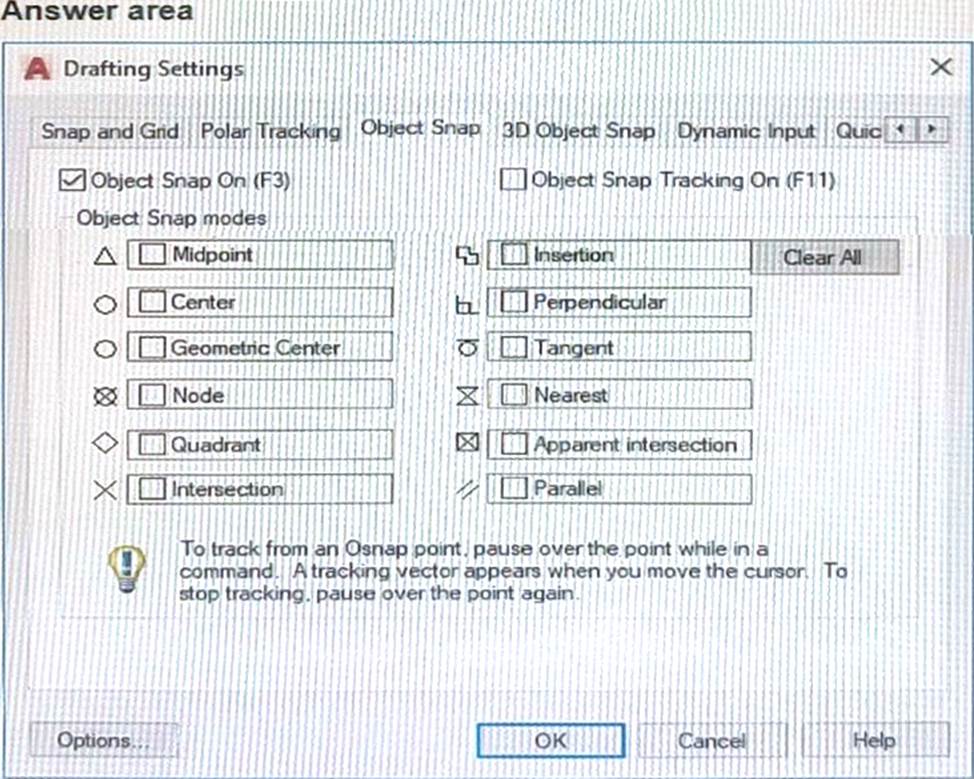
정답: 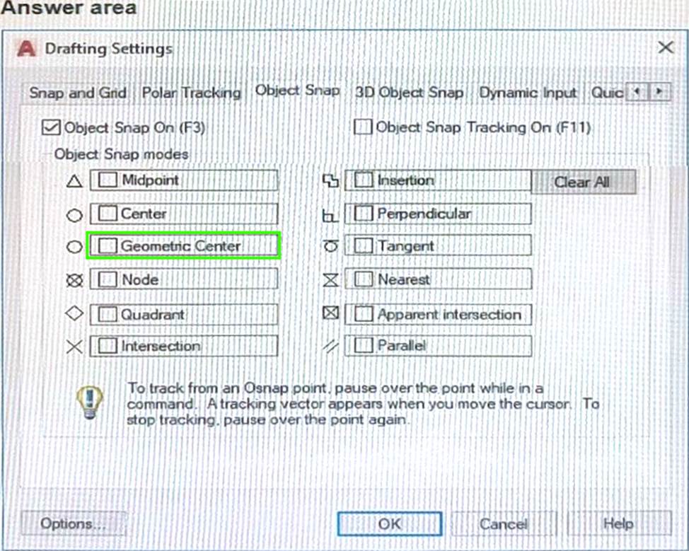
Explanation:
object snaps are modes that allow you to snap to specific points on objects. To snap to the centroid of a closed polyline, you should use the Geometric Center object snap mode. This mode will display an asterisk (*) marker when you move the cursor over the geometric center of a closed polyline or spline.
To use this mode, you can either:
✑ Click on the Object Snap icon in the Status bar and select Geometric Center from the menu.
✑ Type GCE at the command prompt or when prompted for a point and press Enter. Now you can snap to the centroid of a closed polyline by using Geometric Center object snap.
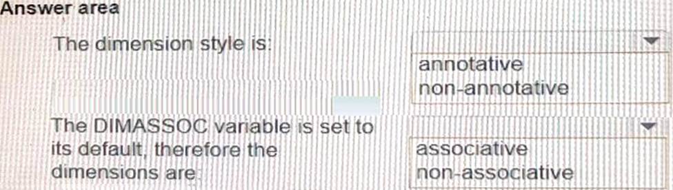
정답: 
Explanation:
Box 1 = annotative
an annotative dimension style is a dimension style that automatically adjusts the size of dimensions based on the viewport scale. An annotative dimension style has an icon next to its name in the Dimension Style Manager dialog box. The dimension style is annotative because the dimension text height is the same for both viewports in the layout, even though they have different viewport scales1.
Box 2 = associative The DIMASSOC is at its default value of 2, therefore the dimensions are associative because they are linked to and update with the measured geometry3.
정답:
Explanation:
a baseline dimension is a linear, angular, or ordinate dimension that is measured from the baseline of a previous or selected dimension. The spacing between baseline dimensions can be set from the Dimension Style Manager, Lines tab, Baseline Spacing (DIMDLI system variable).
The most efficient method to avoid the problem of dimensions being too close together in the future is to use Dimension Style Manager. This will allow you to change the default spacing for all baseline dimensions in your drawing.
https://knowledge.autodesk.com/support/autocad/learn-explore/caas/CloudHelp/cloudhelp/2015/ENU/AutoCAD-Core/files/GUID-D8849F82-C542-45A1-A81C-EE848A0A30D3-htm.html
정답:
Explanation:
polyline is a connected sequence of line segments created as a single object that can contain a width. You can change the width of a polyline by using the PEDIT command.
Based on 3 and 4, LWEIGHT is a command that sets the current lineweight, which is used for new objects and affects objects in the current space only. PLINEWID is a system variable that sets a default polyline width for new polylines. PLINEGEN is a system variable that controls how linetype patterns are generated around vertices.
https://www.roadlesstraveledstore.com/how-do-i-change-the-width-of-a-polyline-in-autocad/
https://knowledgeburrow.com/how-do-i-change-the-width-of-a-polyline-in-autocad/
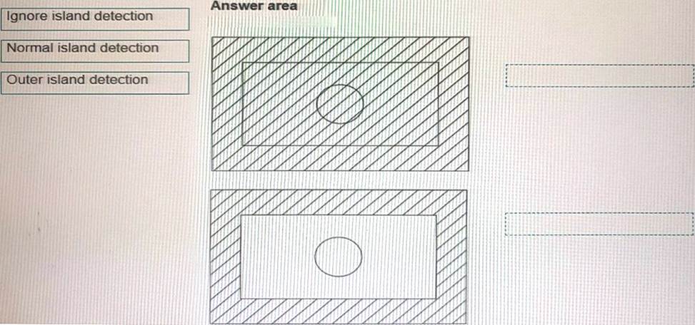
정답: 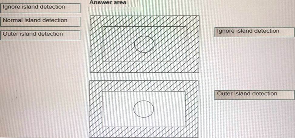
Explanation:
Box 1 = ignore island detection
Box 2 = Outer island detection
https://knowledge.autodesk.com/support/autocad/learn-explore/caas/CloudHelp/cloudhelp/2021/ENU/AutoCAD-Core/files/GUID-981679AC-7097-4724-A30D-33F1CAFDD81D-htm.html
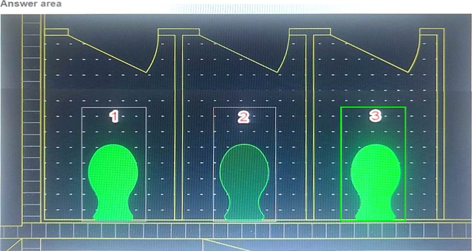
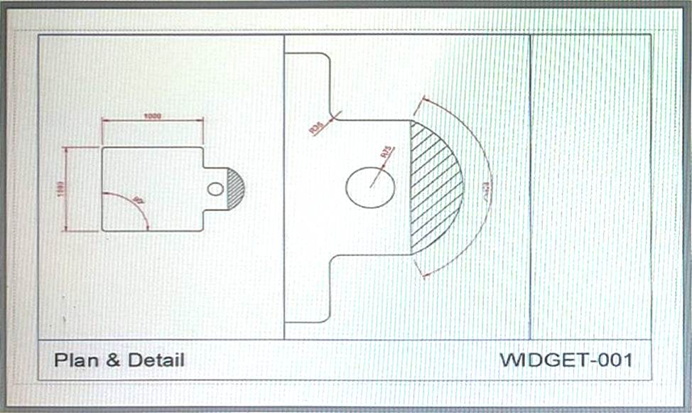
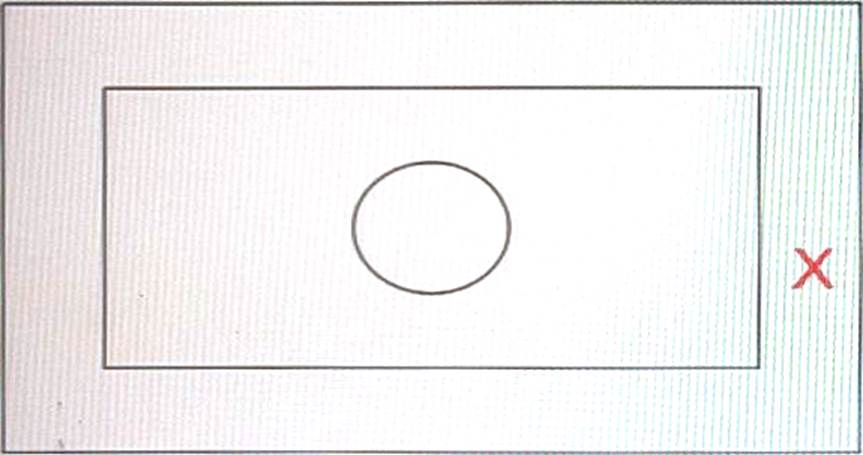
정답: 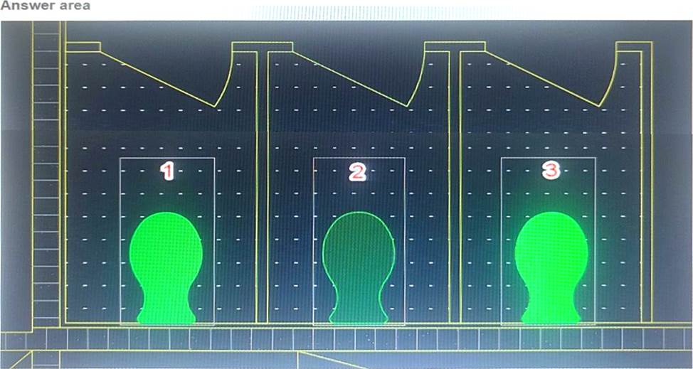
Explanation:
According to the AutoCAD for Design and Drafting documents, layer transparency is a property that makes objects on a layer appear translucent or opaque. The higher the transparency value, the more transparent the layer appears. Therefore, the object that has layer transparency set to 90 is the one that appears the most faded or dimmed in the drawing. In this case, it is the object on the right. You can click on it to select your answer