
매달, 우리는 1000명 이상의 사람들이 시험 준비를 잘하고 시험을 잘 통과할 수 있도록 도와줍니다.
Advanced Deploy VMware vSphere 7.x 온라인 연습
최종 업데이트 시간: 2025년11월17일
당신은 온라인 연습 문제를 통해 VMware 3V0-22.21N 시험지식에 대해 자신이 어떻게 알고 있는지 파악한 후 시험 참가 신청 여부를 결정할 수 있다.
시험을 100% 합격하고 시험 준비 시간을 35% 절약하기를 바라며 3V0-22.21N 덤프 (최신 실제 시험 문제)를 사용 선택하여 현재 최신 17개의 시험 문제와 답을 포함하십시오.
정답: Storage I/O Control v2
Storage I/O Control (SIOC) was initially introduced in vSphere 4.1 to provide I/O prioritization of virtual machines running on a cluster of ESXi hosts that had access to shared storage. It extended the familiar constructs of shares and limits, which existed for CPU and memory, to address storage utilization through a dynamic allocation of I/O queue slots across a cluster of ESXi servers. The purpose of SIOC is to address the ‘noisy neighbor’ problem, i.e. a low priority virtual machine impacting other higher priority virtual machines due to the nature of the application and its I/O running in that low priority VM.
vSphere 5.0 extended SIOC to provide cluster-wide I/O shares and limits for NFS datastores. This means that no single virtual machine should be able to create a bottleneck in any environment regardless of the type of shared storage used. SIOC automatically throttles a virtual machine which is consuming a disparate amount of I/O bandwidth when the configured latency threshold has been exceeded. To allow other virtual machines receive their fair share of I/O bandwidth on the same datastore, a share based fairness mechanism has been created which now is supported on both NFS and VMFS.
vSphere 5.1 introduced a new SIOC feature called Stats Only Mode. When enabled, it doesn’t enforce throttling but gathers statistics to assist Storage DRS. Storage DRS now has statistics in advance for new datastores being added to the datastore cluster & can get up to speed on the datastores profile/capabilities much quicker than before.
Another 5.1 feature was Automatic Threshold Computation. The default latency threshold for SIOC is 30ms. Not all storage devices are created equal so this default was chosen as a sort of “catch-all”. There are certain devices which will hit their natural contention point much earlier than others, for example All Flash Arrays, in which case the threshold should be lowered by the user. However, manually determining the correct latency can be difficult for users. This gave rise to the need for the latency threshold to get automatically determined at a correct level for each device. Using the I/O injector modeling of SIOC, peak throughput and corresponding latency of a datastore is measured. The latency threshold value at which Storage I/O Control will kick in is then set to 90% of this peak value (by default). vSphere administrators can change this 90% to another percentage value or they can still input a millisecond value if they so wish.
The default latency threshold for SIOC can be reduced to as low as 5ms.
SIOC V1 Overview
SIOC V1 is disabled by default. It needs to be enabled on a per datastore level, and it is only utilized when a specific level of latency has been reached. By default, the latency threshold for a datastore is set to 30ms, as mentioned earlier. If SIOC is triggered, disk shares (aggregated from all VMDKs using the datastore) are used to assign I/O queue slots on a per host basis to that datastore. In other words, SIOC limits the number of IOs that a host can issue. The more VMs/VMDKs that run on a particular host, the higher the number of shares, and thus the higher the number of IOs that that particular host can issue. The throttling is done by modifying the device queue depth of the various hosts sharing the datastore. When the period of contention passes, and latency returns to normal values, the device queue depths are allowed to return to default values on each host. SIOC V2 Introduction
Before describing SIOC V2, it should be highlighted that SIOC V1 and SIOC V2 can co-exist on vSphere 6.5. This makes it much simpler when considering upgrades, or migrations between versions. With that in mind, SIOC V2 is considerably different from a user experience perspective when compared to V1. SIOCv2 is implemented using IO Filter framework Storage IO Control category. SIOC V2 can be managed using SPBM Policies.
What this means is that you create a policy which contains your SIOC specifications, and these policies are then attached to virtual machines. Creating an SIOC policy based
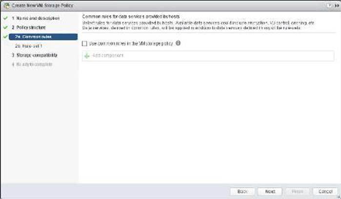
Creating an SIOC policy is done is exactly the same way as building a storage policy for VSAN or Virtual Volumes. Select the VM Storage Policy from the vSphere client home page, and from there select the option to create a new VM Storage Policy. VM Storage Policies in vSphere 6.5 has a new option called “Common Rules”. These are used for configuring data services provided by hosts, such as Storage I/O Control and Encryption.
Use common rules in the VM storage policy
The first step is to click on the check box to enabled common rules. This will then allow you to add components, such as SIOC, to the policy.
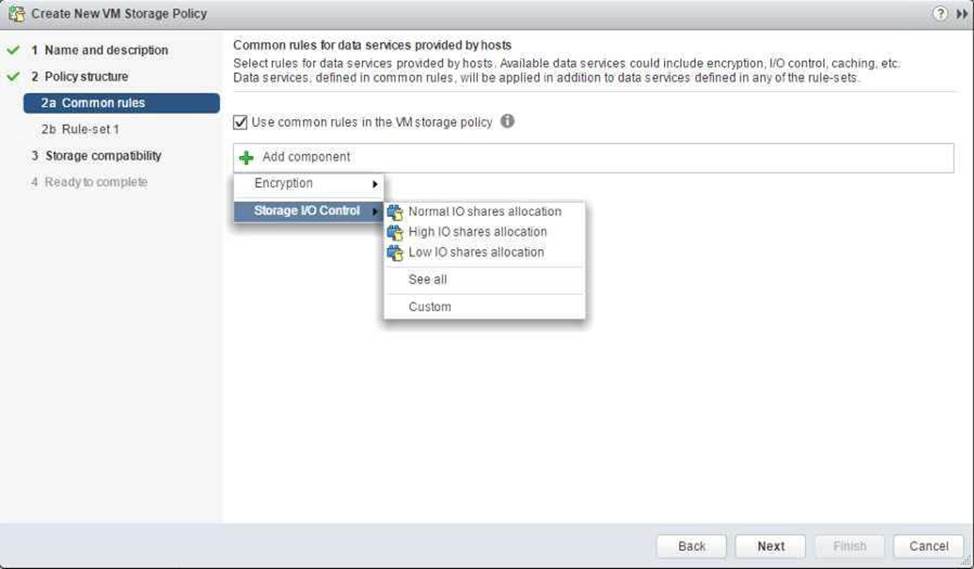
Add Component C Storage I/O Control
In vSphere 6.5, there are two components available for common rules, Encryption and Storage I/O Control. Select Storage I/O Control in this case. Now you can select Normal, High, Low or Custom shares allocation.
This table describes the different Limits,Shares and Reservations associated with each setting:
When the policy has been created, it may be assigned to newly deployed VMs during provisioning,or
to already existing VMs by assigning this new policy to the whole VM (or just an individual VMDK) by
editing its settings. One thing to note is that IO Filter based IOPS does not look at the size of the IO.
For example, there is no normalization so that a 64K IOP is not equal to 2 x 32K IOPS. It is a fixed
value of IOPS irrespective of the size of the IO.
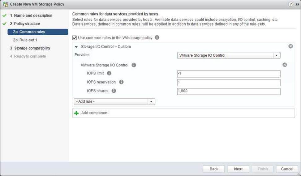
Custom Allocation
If neither of the values in the Normal, High, Low allocations is appropriate, there is the ability to create custom settings for these values. In a custom setting, IOPS limit and IOPS reservation are both set to -1, implying unlimited. These may be modified as required.
Advanced Options
SchedCostUnit
This is an advanced parameter that was created for SIOC V1 only. SIOC V2 does not have SchedCostUnit implemented. For V1, SchedCostUnit determines the unit size (normalized size) of an IO operation for scheduling, and it is currently a constant value of 32K. This constant value, however, may not satisfy different requirements from different customers. Some customers may want to set this unit size to 4K. Other customers may want to set it up to 256K.
To satisfy these different requirements, SchedCostUnit is now configurable. It defaults to an IO size value of 32K, and allowable values range between 4K to 256K.
The SchedCostUnit dictates how requests are counted. A request with size <= SchedCostUnit counts as a single I/O. Anything greater than SchedCostUnit will be counted as 2 or more requests.
For example, by changing the SchedCostUnit from 32K to 64K, the number of IOPS observed will
halve. The size of the IO can be set using the:
“esxcli system settings advanced set -o /Disk/SchedCostUnit -i 65536” and verified by using the”
"esxcli system settings advanced list -o /Disk/SchedCostUnit”
command. SIOC V2 counts guest IO directly. IOPS will be counted based on IO count, regardless of
the IO size.
SchedReservationBurst
When limits are set on VMDKs, requests could have high average latency because the limit was enforced at a high (per request) granularity. This was due to the strict enforcement on a VM getting its share of IOs in interval of 1 second/L, where L is the user specified limit. The issue is more visible in fast storage, such as flash arrays. It was noted that SIOC V2 did not perform well when presented with a “bursty” workload on fast storage.
This SchedReservationBurst setting relaxes that constraint so a VM get its share of IOs at any time
during a 1 second window, rather than enforce strict placement of IOs in intervals of 1/L. BURST
option is turned-on by default.
SIOC V2 Limitations
In this initial release of SIOC V2 in vSphere 6.5, there is no support for vSAN or Virtual Volumes. SIOC v2 is only supported with VMs that run on VMFS and NFS datastores.
정답: VMware vSphere ESXi can use locally attached SSDs (Solid State Disk) and flash devices in multiple ways. Since SSDs offer much higher throughput and much lower latency than traditional magnetic hard disks the benefits are clear. While offering lower throughput and higher latency, flash devices such as USB or SATADOM can also be appropriate for some use cases. The potential drawback to using SSDs and flash device storage is that the endurance can be significantly less than traditional magnetic disks and it can vary based on the workload type as well as factors such as the drive capacity, underlying flash technology, etc.
This KB outlines the minimum SSD and flash device recommendations based on different technologies and use case scenarios.
SSD and Flash Device Use Cases
A non-exhaustive survey of various usage models in vSphere environment are listed below. Host swap cache
This usage model has been supported since vSphere 5.1 for SATA and SCSI connected SSDs. USB and low end SATA or SCSI flash devices are not supported.
The workload is heavily influenced by the degree of host memory over commitment. Regular datastore
A (local) SSD is used instead of a hard disk drive.
This usage model has been supported since vSphere 7.0 for SATA and SCSI connected SSDs.
There is currently no support for USB connected SSDs or for low end flash devices regardless of
connection type.
vSphere Flash Read Cache (aka Virtual Flash)
This usage model has been supported since vSphere 5.5 for SATA and SCSI connected SSDs.
There is no support for USB connected SSDs or for low end flash devices.
vSAN
This usage model has been supported since vSphere 5.5 for SATA and SCSI SSDs. For more information, see the vSAN Hardware Quick Reference Guide.
vSphere ESXi Boot Disk
A USB flash drive or SATADOM or local SSD can be chosen as the install image for ESXi, the vSphere hypervisor, which then boots from the flash device.
This usage model has been supported since vSphere 3.5 for USB flash devices and vSphere 4.0 for SCSI/SATA connected devices.
Installation to SATA and SCSI connected SSD, SATADOM and flash devices creates a full install image which includes a logging partition (see below) whereas installation to a USB device creates a boot
disk image without a logging partition.
vSphere ESXi Coredump device
The default size for the coredump partition is 2.5 GiB which is about 2.7 GB and the installer creates a coredump partition on the boot device device for vSphere 5.5 and above. After installation the partition can be resized if necessary using partedUtil. For more information, see the vSphere documentation.
Any SATADOM or SATA/SCSI SSD may be configured with a coredump partition.
This usage model has been supported from vSphere 3.5 for boot USB flash devices and since vSphere 4.0 for any SATA or SCSI connected SSD that is local.
This usage model also applies to Autodeploy hosts which have no boot disk.
vSphere ESXi Logging device
A SATADOM or local SATA/SCSI SSD is chosen as the location for the vSphere logging partition
(/scratch partition). This partition may be but need not be on the boot disk and this applies to Autodeploy hosts which lack a boot disk.
This usage model has been supported since vSphere 7.0 for any SATA or SCSI connected SSD that is local. SATADOMs that meet the requirement set forth in Table 1 are also supported.
This usage model can be supported in a future release of vSphere for USB flash devices that meet the requirement set forth in Table 1.
SSD Endurance Criteria
The flash industry often uses Tera Bytes Written (TBW) as a benchmark for SSD endurance. TBW is the number of terabytes that can be written to the device over its useful life. Most devices have distinct TBW ratings for sequential and random IO workloads, with the latter being much lower due to Write Amplification Factor (WAF) (defined below). Other measures of endurance commonly used are DWPD (Drive Writes Per Day) and P/E (Program/Erase) cycles.
Conversion formulas are provided here:
Converting DWPD (Drive Writes Per Day) to TBW (Terabytes Written):
TBW = DWPD * Warranty (in Years) * 365 * Capacity (in GB) / 1,000 (GB per TB)
Converting Flash P/E Cycles per Cell to TBW (Terabytes Written):
TBW = Capacity (in GB) * (P/E Cycles per Cell) / (1,000 (GB per TB) * WAF)
WAF is a measure of the induced writes caused by inherent properties of flash technology. Due to the difference between the storage block size (512 bytes), the flash cell size (typically 4KiB or 8KiB bytes) and the minimum flash erase size of many cells one write can force a number of induced writes due to copies, garbage collection, etc. For sequential workloads typical WAFs fall in the range of single digits while for random workloads WAFs can approach or even exceed 100. Table 1 contains workload characterization for the various workloads excepting the Datastore and vSphere Flash Read Cache workloads which depend on the characteristics of the Virtual Machines workloads being run and thus cannot be characterized here. A WAF from the table can be used with the above P/E to TBW formula.
정답: Select Menu > Policies and Profiles, and under Policies and Profiles, click VM Customization Specifications.
Click the Create a new specification icon.
The New VM Guest Customization Specification wizard opens.
On the Name and target OS page, enter a name and description for the customization specification and select Windows as a target guest OS.
(Optional) Select the Generate a new security identity (SID) option and click Next.
A Windows Security ID (SID) is used in some Windows operating systems to uniquely identify systems and users. If you do not select this option, the new virtual machine has the same SID as the virtual machine or template from which it was cloned or deployed.
Duplicate SIDs do not cause problems when the computers are part of a domain and only domain user accounts are used. However, if the computers are part of a Workgroup or local user accounts are used, duplicate SIDs can compromise file access controls. For more information, see the documentation for your Microsoft Windows operating system.
On the Set Registration Information page, enter the virtual machine owner’s name and organization and click Next.
On the Computer name page, enter a computer name for the guest operating system and a domain name.
The operating system uses the computer name to identify itself on the network. On Linux systems, it is called the host name.
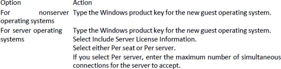
On the Windows license page, provide licensing information for the Windows operating system and click Next.
On the Set Administrator Password page, configure the administrator password for the virtual machine and click Next.
Enter a password for the administrator account and confirm the password by typing it again. (Optional) Select the Automatically logon as Administrator check box to log users in to the guest operating system as Administrator, and select the number of times to log in automatically. On the Time zone page, select the time zone for the virtual machine and click Next.
(Optional) On the Run Once page, specify commands to run the first time a user logs in to the guest operating system and click Next.
See the Microsoft Sysprep documentation for information about RunOnce commands.
On the Network page, select the type of network settings to apply to the guest operating system and click Next.
Select Use standard network settings so that vCenter Server configures all network interfaces from a DHCP server by using the default settings.
Select Manually select custom settings and configure each network interface yourself.
Select a network adapter from the list or add a new one.
For the selected NIC, click the vertical ellipsis icon and select Edit.
The Edit Network dialog box opens.
Click the IPv4 tab to configure the virtual machine to use IPv4 network.
You can configure all the settings at that stage or you can select the Prompt the user for an IPv4 address when the specification is used option. In that case, vCenter Server prompts for an IP address when you select to apply that customization specification during cloning or deployment. With that option, you can also configure the gateways during cloning or deployment. Click the IPv6 tab to configure the virtual machine to use IPv6 network.
You can configure all the settings at that stage or you can select the Prompt the user for an address when the specification is used option. In that case, vCenter Server prompts for an IP address when you select to apply that customization specification during cloning or deployment. With that option, you can also configure the gateways during cloning or deployment.
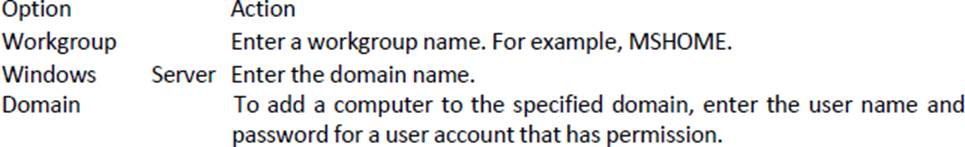
Option Workgroup Windows Domain
Click the DNS tab to specify DNS server details.
Click WINS to specify primary and secondary WINS server information.
Click OK to close the Edit Network dialog box.
On the Set Workgroup or Domain page, select how the virtual machine participates in the network and click Next.
On the Ready to complete page, review the details and click Finish to save your changes.
정답: The Update Manager displays system managed baselines that are generated by vSAN. These baselines appear by default when you use vSAN clusters with ESXi hosts of version 6.0 Update 2 and later in your vSphere inventory. If your vSphere environment does not contain any vSAN clusters, no system managed baselines are created.
The system managed baselines automatically update their content periodically, which requires Update Manager to have constant access to the Internet. The vSAN system baselines are typically refreshed every 24 hours.
You use system managed baselines to upgrade your vSAN clusters to recommended critical patches, drivers, updates or the latest supported ESXi host version for vSAN.
System managed baselines cannot be edited or deleted. You do not attach system managed baselines to inventory objects in your vSphere environment. You can create a baseline group of multiple system managed baselines, but you cannot add any other type of basline to that group. Similarly, you cannot add a system managed baseline to a baseline group that contains upgrade, patch, and extension baselines.
정답: Before you can use vSphere ESXi Image Builder with the vSphere Web Client, you must verify that the
service is enabled and running.
Procedure
Log in to your vCenter Server system by using the vSphere Web Client.
On the vSphere Web Client Home page, click Administration.
Under System Configuration click Services.
Select ImageBuilder Service, click the Actions menu, and select Edit Startup Type.
On Windows, the vSphere ESXi Image Builder service is disabled. In the Edit Startup Type window, select Manual or Automatic to enable Auto Deploy.
On the vCenter Server Appliance, the vSphere ESXi Image Builder service by default is set to Manual.
If you want the service to start automatically upon OS startup, select Automatic.
If you select the manual startup type, you must start the service manually upon OS startup every time you want to use the service.
(Optional) Click the Start the service icon.
(Optional) If you want to use vSphere ESXi Image Builder with thevSphere Web Client, log out of the vSphere Web Client and log in again.
The Auto Deploy icon is visible on the Home page of the vSphere Web Client